BGP VPLS deep dive. Nokia SR OS & Juniper#
It may very well be that VPLS days are numbered and EVPN is to blame. Nevertheless, it would be naive to expect VPLS extinction in the near future. With all its shortcomings VPLS is still very well standardized, interop-proven and has a huge footprint in MPLS networks of various scale.
In this post I will cover theory and configuration parts for one particular flavor of VPLS signalling - BGP VPLS (aka Kompella VPLS) defined in RFC4761. I'll start with simple single home VPLS scenario while multi-homing techniques and some advanced configurations might appear in a separate post later.
In this topic the following SW releases were used:
- Nokia (Alcatel-Lucent) VSR 14.0.R4
- Juniper vMX 14.1R1.10
BGP VPLS Basics#
Virtual Private LAN Service (VPLS) is seen like an Ethernet LAN by the customers of a Service Provider. However, in a VPLS, not all of the customers are connected to a single LAN; they may be spread across a metro or wide area network. In essence, a VPLS glues together several individual LANs across a packet switched network to appear and function as a single LAN. This is accomplished by incorporating MAC address learning, flooding, and forwarding functions in the context of pseudowires that connect these individual LANs.
The entire VPLS service behaves like a big switch with distributed MAC learning intelligence implemented on each PE, and as in a switch, MAC learning happens in a dataplane.

The following two types of interfaces are typical for VPLS:
- Attachment Circuits (AC) - circuits connecting Customer Edge (CE) devices to Provider Edge (PE) routers. PE routers often called VPLS Edge (VE) devices in VPLS terminology.
- Pseudowires (PW) - circuits connecting PEs between each other
In the context of a given VPLS instance, a PE can have one or more local ACs, and one or more PWs toward remote PEs. Full-mesh of transport tunnels between PEs is required.
In Kompella VPLS, BGP is a key enabler and is responsible for:
- Auto-discovery: process of finding all PE routers participating in a VPLS instance;
- Signalling: the setup and tear-down of pseudowires (PW) that constitute the VPLS service.
Auto-discovery#
Each PE "discovers" which other PEs are part of a given VPLS by means of BGP. This allows each PE's configuration to consist only of the identity of the VPLS instance established on this PE, not the identity of every other PE in that VPLS instance. Moreover, when the topology of a VPLS changes, only the affected PE's configuration changes; other PEs automatically find out about the change and adapt.
The Route Target community is used to identify members of a VPLS. A PE announces that it belongs to
VPLS Vby annotating its NLRIs forVPLS Vwith Route TargetRT, and acts on this by accepting NLRIs from other PEs that have Route TargetRT. A PE announces that it no longer participates inVPLS Vby withdrawing all NLRIs that it had advertised with Route TargetRT.
Signalling#
Once discovery is done, each pair of PEs in a VPLS must be able to establish (and tear down) pseudowires to each other, i.e., exchange (and withdraw) demultiplexors. This process is known as signaling. Signaling is also used to transmit certain characteristics of the pseudowires that a PE sets up for a given VPLS.
BGP Update message carrying BGP VPLS NLRI (AFI:25, SAFI:65) is used to signal VPLS membership and multiplexors for a VPLS service:

Let's expand some of the fields of the BGP VPLS NLRI:
- Route Distinguisher - used to differentiate between customer NLRIs thus should be unique for every VPLS service.
- VE ID - unique identifier (aka site-id), manually assigned to every VPLS Edge device.
- VE Block Offset, VE Block Size and Label Base are used for calculating the service label (multiplexor).
Label Blocks#
Using a distinct BGP Update message to send a demultiplexor to each remote PE would require the originating PE to send N such messages for N remote PEs. In order to minimize the control plane load original standard introduced Label Blocks which drastically reduce the amount of BGP Update messages. A label block is a set of demultiplexor labels used to reach a given VE ID.
A single BGP VPLS NLRI signals a label block which consists of:
- VE ID - manually assigned to VE device identifier
- Label Base (LB) - first label assigned to a label block
- VE Block Size (VBS) - number of labels assigned to a label block. Vendor-dependant value, Nokia and Juniper both use Block Size of 8.
- VE Block Offset (VBO) - first VE ID assigned to a label block
A contiguous label block defined by <LB, VBO, VBS> is the set {LB+VBO, LB+VBO+1, ..., LB+VBO+VBS-1}. Thus, instead of a single large label block to cover all VE IDs in a VPLS, one can have several label blocks, each with a different label base.

Pseudowire setup process#
Section 3.2.3 of RFC4761 highlights the steps VE routers go through during PW setup/teardown. Lets see by an example how PW setup takes places in a BGP VPLS between routers VE1 and VE7.

-
Router VE1 is part of VPLS
BLUEand has VPLS service configured with the following parameters:Upon a service config router VE1 sends BGP Update message to all its BGP peers with NLRI describing its label block. Since for this moment VE1 has no knowledge about any other router participating in
VPLS BLUEservice it sends only one NLRI. This NLRI covers a label block which has its own VE-ID (refer to the figure 40) -
When VE10 router boots with the same
VPLS BLUEservice configured using the following params:it sends BGP Update to all its peers. Again, since VE10 hasn't seen any VE routers yet, it will send only one NLRI with a label block which its VE-ID reside in.
-
VE1 receive BGP Update send by VE10 and since route-target community is the same on both routers VE1 accepts it. Then VE1 performs a check whether the NLRI it received from VE10 can be used for PW setup (see Fig. 50, step 3). Since the result of the check returned false, VE1 can't use received NLRI from VE10 for PW setup towards it.

- By receiving an update from VE10, VE1 now has knowledge of VE10 existence and checks if it has sent label block which contains a label for VE10. As stated in Fig. 40, VE1 sent label block containing information that can be used by routers with VE-ID from 1 to 8, thus VE10 can not setup PW using this label block. VE1 then sends another BGP Update with NLRI covering VE-IDs from 9 to 16 to satisfy VE10 needs.
- Router VE10 performs the same check against received NLRI. This time the check is passed and VE10 can calculate a label (multiplexor) which it should use for PW from VE10 to VE1.
- As in step 4, VE10 generates additional BGP Update with NLRI covering VE1 range.
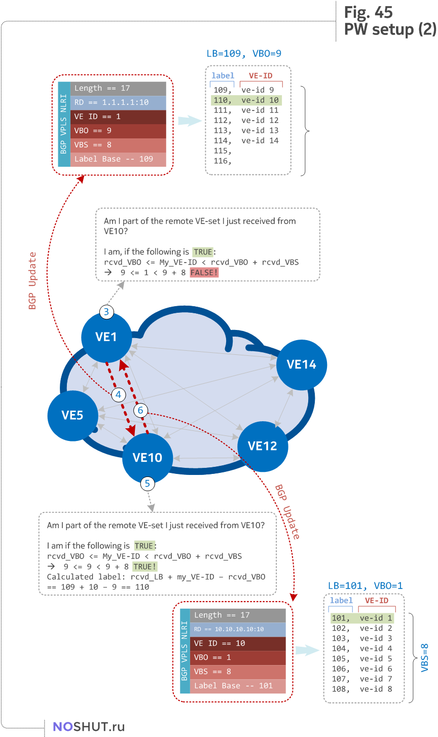
This enables PW to setup from VE1 to V10 and from VE10 to VE1 by using MPLS labels calculated on each router independently.
Layer 2 Info Extended community#
Additional extended community is used in VPLS service establishment - originally Layer 2 Info extended community was defined in section 3.2.4. It is used to signal control information about the pseudowires to be setup for a given VPLS. Two additional bits (D, F) later were introduced by vpls-multihoming draft.
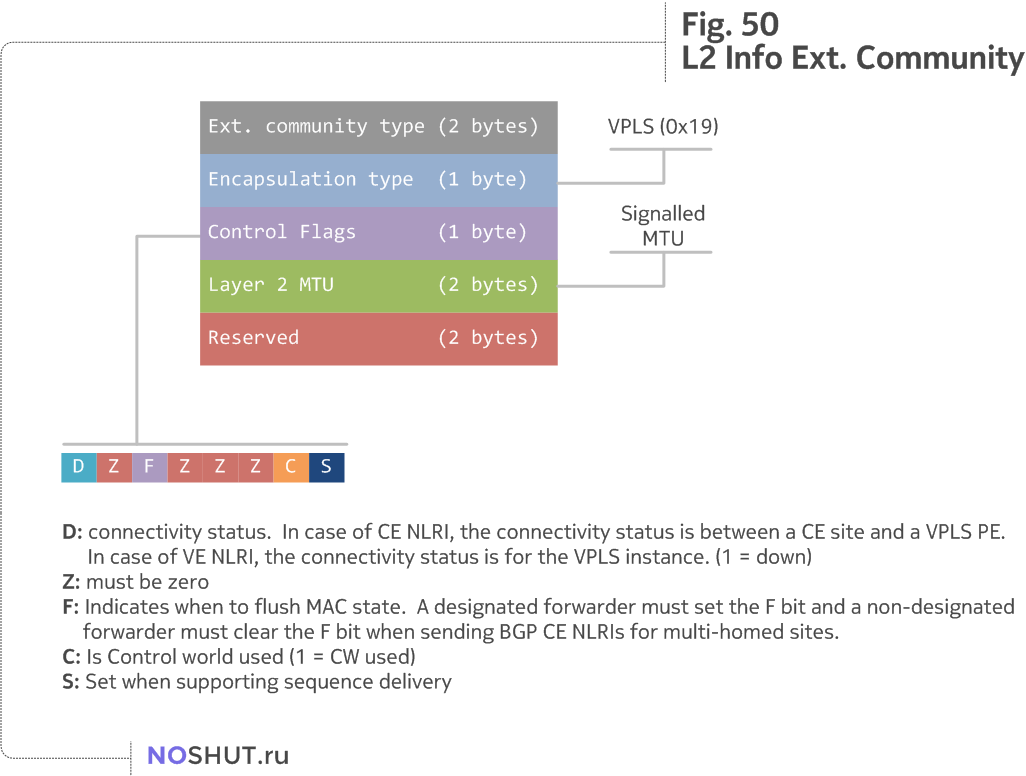
MTU considerations#
One of the important fields in L2 Info community is the Layer 2 MTU. VE routers signal MTU which can be carried within VPLS service, moreover some router platforms will bring service into down state if the MTU values mismatch. Usually you can find configuration knobs which will turn off MTU matching, though it is better to keep MTU consistent between endpoints.
Interesting fact is that Juniper routers (at least vMX 14.1) defaults to signal MTU=0 (as seen in Figure 80), which wont bring service down, because this means do not consider MTU value. Again, in vMX 14.1 there is no way to signal any particular MTU value for VPLS service, though starting with 15.1 it is possible with mtu keyword.
VLAN tag multiplexing#
To understand how ethernet frames are handled by PE and transported over PW we need to cover possible variations of frames on AC, as well as different modes of PW operation.
Frames from the CE devices can be seen on the attachment circuits in different flavours:
- untagged
- tagged (dot1q, q-in-q) by CE device itself
- additionally tagged by some SP's aggregation device (SVLAN put by L2 agg. device)
When it comes to PW operation modes, RFC 4448 gives us two options: raw and tagged. Thus, we can distinguish two cases regarding tagged frames coming from AC:
-
The tag is service-delimiting.
This means that the tag was placed on the frame by some piece of service provider-operated equipment, and the tag is used by the service provider to distinguish the traffic. For example, LANs from different customers might be attached to the same service provider switch, which applies VLAN tags to distinguish one customer's traffic from another's, and then forwards the frames to the PE. -
The tag is not service-delimiting.
This means that the tag was placed in the frame by a piece of customer equipment, and is not meaningful to the PE.
RFC 4448 explains further possible scenarios actions:
- PW is operating in raw mode (aka Ether):
- Service-delimiting tags are NEVER sent over the PW, if tag is present, it MUST be stripped before sending on PW
- When sending a frame on AC, PE may add service-delimiting tag, but can not strip or rewrite any existing tags present on a frame
- PW is operating in tagged mode (aka VLAN):
- PW MUST have a service-delimiting VLAN tag. If service-delimiting tag is not present, the PE must prepend the frame with a dummy VLAN tag before sending the frame on the PW
- When sending a frame on AC, PE may rewrite or strip tag entirely
- Whether or not the tag is service-delimiting is determined by local configuration on the PE
- Service-delimiting tag have local to PE-CE interface significance
- Non-service-delimiting tags are passed transparently across the PW as part of the payload
VPLS data plane#
This topic is focusing on VPLS data plane encapsulation, as defined in RFC 4448 - Encapsulation Methods for Transport of Ethernet over MPLS Networks.
MAC learning#
VPLS is a multipoint service with a MAC learning on a data plane. This means that the entire Service Provider network should appear as a single logical learning bridge (Ethernet switch) for each VPLS that the SP network supports. The logical ports for the SP "bridge" are the AC as well as the PW on a PE. As a result of MAC learning, bridges populate a MAC table in which they keep track of the interface (or PW) where each unicast MAC is reachable.
Aging, Flooding, BUM traffic#
VPLS PEs SHOULD have an aging mechanism to remove a MAC address associated with a logical port. Aging reduces the size of a VPLS MAC table to just the active MAC addresses. When a bridge receives a packet to a destination that is not in its FIB, it floods the packet on all the other ports (process known as replication). Frames that should be flooded are Broadcast, Unknown unicast and Multicast
- Broadcast frames have destination MAC address
ff:ff:ff:ff:ff:ff. - Multicast frames have a destination MAC address whose first octet has its last bit set to one
To avoid loops during replication process split-horizon rule should be honored: A frame received on a PW is never sent back on the same or any other PW (default, but configurable behavior).
Case study: Single-homed VPLS#
Enough with theory, time to practice some VPLS! I will start with a simple case of two CE routers (CE1 and CE2) connected to a Service Provider's PE routers (R1, R2) configured with a VPLS service. Refer to Fig. 60 outlining lab topology for this case. It is assumed that ISIS and LDP are configured and operational.

Refer to these baseline configurations:
BGP configuration#
This one is really simple. All we need is to configure MP-iBGP peering between PEs and RR with L2 VPN family enabled:
R1 (Nokia)
*A:R1>config>router# info
#--------------------------------------------------
echo "IP Configuration"
#--------------------------------------------------
## < Output omitted for brevity >

        autonomous-system 65000
#--------------------------------------------------


*A:R1>config>router>bgp# info
----------------------------------------------
            connect-retry 1
            min-route-advertisement 1
            rapid-withdrawal
            rapid-update l2-vpn
            group "RR"
                family l2-vpn
                enable-peer-tracking
                neighbor 3.3.3.3
                    type internal
                exit
            exit
            no shutdown
----------------------------------------------
R3 Route reflector (Nokia)
*A:R3>config>router# info
#--------------------------------------------------
echo "IP Configuration"
#--------------------------------------------------
## < Output omitted for brevity >

        autonomous-system 65000
#--------------------------------------------------


A:R3>config>router>bgp# info
----------------------------------------------
            family l2-vpn
            connect-retry 1
            min-route-advertisement 1
            enable-peer-tracking
            rapid-withdrawal
            rapid-update l2-vpn
            group "RRC"
                cluster 3.3.3.3
                neighbor 1.1.1.1
                    type internal
                exit
                neighbor 2.2.2.2
                    type internal
                exit
            exit
            no shutdown
----------------------------------------------
R2 (Juniper)
root@R2# show routing-options | grep auto
autonomous-system 65000;

root@R2# show protocols bgp
group RR {
    type internal;
    family l2vpn {
        signaling;
    }
    neighbor 3.3.3.3;
}
Interface configuration#
To demonstrate vlan-normalization methods I used two different vlans on attachment circuits connected to R1 and R2. Our CE1 and CE2 devices have simple dot1q interfaces addressed in this way:
- CE1 has interface
toCE2with address192.168.1.1/24,VLAN 10 - CE1 has interface
toCE1with address192.168.1.2/24,VLAN 600
Router R1 has vlan 10 on its AC, while R2 configured with vlan-id 600 (on Juniper vlan ids values for VPLS interfaces must be > 512).
Nokia routers do not differ if interface is going to be used in any particular service or in no service at all, therefore the configuration steps are obvious. The part which enables particular ethernet encapsulation (802.1q in this case) is done under port configuration:
R1:
A:R1# configure port 1/1/2
A:R1>config>port# info
----------------------------------------------
        ethernet
            mode hybrid  ## hybrid means that port can act as an access & network port
            encap-type dot1q
        exit
        no shutdown
----------------------------------------------
Configuration of Vlan-id 10 attachment to a VPLS service will be done later in the VPLS configuration section.
Note, that Ethernet MTU on Nokia routers includes Ethernet header. This means that, for instance, interface with MTU 2000 will be able to put on wire exactly 2000 bytes, for example:
TOTAL 2000B == Frame 54: 2000 bytes on wire (16000 bits), 2000 bytes captured (16000 bits) on interface 0
14B         == Ethernet II, Src: 50:01:00:04:00:01 (50:01:00:04:00:01), Dst: 50:01:00:05:00:01 (50:01:00:05:00:01)
4B          == 802.1Q Virtual LAN, PRI: 7, CFI: 0, ID: 10
20B         == Internet Protocol Version 4, Src: 192.168.1.1, Dst: 192.168.1.2
1962B       == Internet Control Message Protocol
In contrast with Nokia, Juniper's configuration of interface is done in a different way.
root@R2# show interfaces ge-0/0/1
flexible-vlan-tagging;
encapsulation flexible-ethernet-services;
unit 600 {
    encapsulation vlan-vpls;
    vlan-id 600;
}
In Juniper you have to specify encapsulation vlan-vpls under the interface's configuration for a logical unit you're going to use as an AC.
Service configuration#
Now to the main course, service configuration. Both Nokia and Juniper has some vendor-specifics and different defaults worth mentioning.
Let's take one section at a time and discuss the details. On R1 I configured VPLS service with id 10. The same id I used for RD and RT.
A:R1# configure service vpls 10
A:R1>config>service>vpls# info
----------------------------------------------
            bgp
                route-distinguisher 1.1.1.1:10
                route-target export target:65000:10 import target:65000:10
                pw-template-binding 11
                exit
            exit
BGP section of VPLS service has RD/RT values which used for route distinguishing between different VPLS services and auto-discovering based on Route Target. What is interesting here is pw-template-binding keyword. In SROS we use pseudowire templates to describe pseudowire characteristics. Based on this template PW will later bind to a VPLS service and established.
A:R1# configure service pw-template 11
A:R1>config>service>pw-template# info
----------------------------------------------
            controlword
            force-vlan-vc-forwarding
            split-horizon-group "mesh"
            exit
----------------------------------------------
The MPLS transport tunnel between PEs can be signaled using LDP or RSVP-TE. LDP based pseudowires can be automatically instantiated. RSVP-TE based SDPs have to be pre-provisioned. In this post I rely on automatically created LDP LSP. Using this mechanism SDPs will be auto-instantiated.
A keyword controlword indicates that control word must be used in dataplane. A pseudowire template is required containing a split horizon group. Each SDP created with this template is contained within a split horizon group so that traffic cannot be forwarded between them.
By using force-vlan-vc-forwarding command we force a VE router to push service-delimiting vlan-id when sending data on PW (it is PW vlan-tagged mode). By default service-delimiting tag will be stripped off (equals to PW raw mode).
Next section carries bgp-vpls specific commands:
In this section VPLS Edge name should be configured along with ve-id. What is specific to Nokia SR OS is the necessity to configure max-ve-id value.
The choice of ve-id is crucial in ensuring efficient allocation of de-multiplexer labels. The most efficient choice is for ve-ids to be allocated starting at 1 and incrementing for each PE as the following section explains.
The max-ve-id value determines the range of the ve-id value that can be configured. If a PE receives a BGP-VPLS update containing a ve-id with a greater value than the configured max-ve-id, then the update is dropped and no service labels are installed for this ve-id.
Note: For Juniper it is not mandatory (but possible) to configure maximum VE devices in a service.
The rest of the service configuration goes like this:
Important part here is sap (service access point) binding. Command sap 1/1/2:10 basically tells that frames coming in port 1/1/2 encapsulated with vlan-id 10 will be attached to this VPLS service. Note, that vlan-id 10 is a service delimiter. Read more about processing of vlan tags here.
Since our topology is loop-free we do not need to run STP, thus it is shutdowned.
Juniper configuration of a service is as follows. A couple of lines need to be explained, while most of them are pretty standard:
root@R2# show routing-instances VPLS-BLUE
instance-type vpls;
vlan-id 10;
interface ge-0/0/1.600;
route-distinguisher 2.2.2.2:10;
vrf-target target:65000:10;
protocols {
    vpls {
        control-word;
        no-tunnel-services;
        site CE2 {
            site-identifier 2;  ## VE-ID
            interface ge-0/0/1.600;
        }
    }
}
For VPLS service Juniper offers two types of routing instances: vpls and virtual-switch. Differences between them covered for example in the MPLS in the SDN Era book chapter 7. I used a simple vpls instance.
The reason for no-tunnel-services covered in this article.
vlan-id 10 statement used for vlan-normalization, refer to the next section for the details.
VLAN handling in VPLS#
Most common problem with VPLS services are VLAN handling when vlan-id on attachment circuits differs. And our topology is a perfect example of this, two ACs use different vlans (10 on R1 and 600 on R2). At the same time these vlan-ids are of service-delimiting purpose, meaning that they are not CE provisioned vlans, but actually SPs assigned for multiplexing different customers/services on a single AC.
Handling of service-delimiting vlans is different on Nokia and Juniper. Take a look at Fig. 70 and refer once again to MPLS in the SDN Era book chapter 7 where each of VLAN modes discussed in details:

Control plane walk through#
To assemble all the pieces discussed earlier into a picture I will cover things that happen in control and data planes during the VPLS service creation and operation.
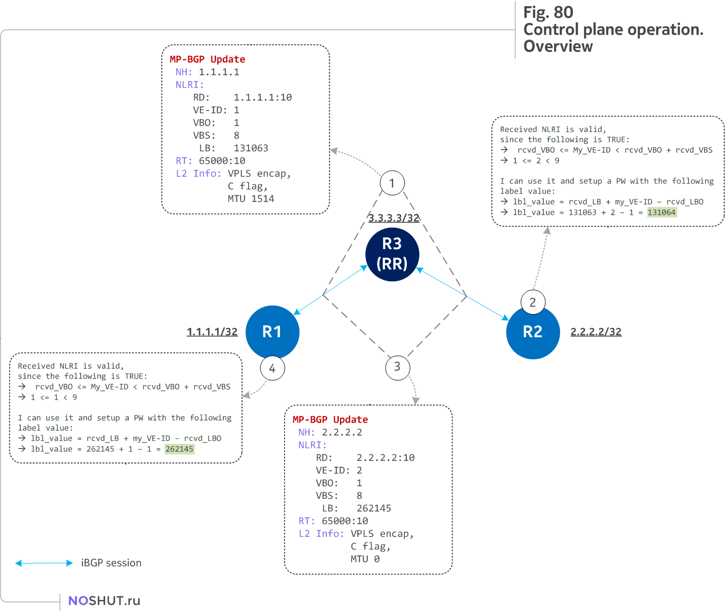
Step 1
For simplicity of discussion lets assume that router R1 has its VPLS service configured first and send MP-BGP Update to Route Reflector. BGP Update consists of elements we have covered in previous sections of this post.
Worth mentioning here is that R1 sends only one label block of size 8 (despite that max-ve-id has been configured for 10 VE devices). This is the result of optimization techniques, router does not send all the blocks, it will send ones that necessary once it receive an update message with CE-ID which is not part of blocks advertised by a router so far.
Step 2
R2 receives update from R1 (via R3) and goes through PW setup process discussed earlier. At this step R2 calculates a service MPLS label it will use in the data plane.
Step 3
Now operator enables VPLS service on R2 and its R2's turn to send BGP Update towards R1.
Step 4
R1 follows the same procedure as R2 did in step 2.
At the end of control plane messages exchange we should have a pseudowire established with a certain characteristics and the service status should be healthy. Lets ensure that from control plane perspective VPLS service is up and running on both platforms.
Getting status of VPLS service with id 10:
A:R1# show service id 10 base

===============================================================================
Service Basic Information
===============================================================================
Service Id        : 10                  Vpn Id            : 0
Service Type      : VPLS
Name              : (Not Specified)
Description       : (Not Specified)
Customer Id       : 1                   Creation Origin   : manual
Last Status Change: 03/13/2016 07:59:09
Last Mgmt Change  : 03/13/2016 07:59:34
Etree Mode        : Disabled
Admin State       : Up                  Oper State        : Up
MTU               : 1514                Def. Mesh VC Id   : 10
SAP Count         : 1                   SDP Bind Count    : 1
Snd Flush on Fail : Disabled            Host Conn Verify  : Disabled
SHCV pol IPv4     : None
Propagate MacFlush: Disabled            Per Svc Hashing   : Disabled
Allow IP Intf Bind: Disabled
Fwd-IPv4-Mcast-To*: Disabled            Fwd-IPv6-Mcast-To*: Disabled
Def. Gateway IP   : None
Def. Gateway MAC  : None
Temp Flood Time   : Disabled            Temp Flood        : Inactive
Temp Flood Chg Cnt: 0
SPI load-balance  : Disabled
TEID load-balance : Disabled
Src Tep IP        : N/A
VSD Domain        : <none>

-------------------------------------------------------------------------------
Service Access & Destination Points
-------------------------------------------------------------------------------
Identifier Type         AdmMTU  OprMTU  Adm  Opr
-------------------------------------------------------------------------------
sap:1/1/2:10                             q-tag        8704    8704    Up   Up
sdp:17407:4294967293 SB(2.2.2.2)         BgpVpls      0       8678    Up   Up
===============================================================================
Basic information about a service shows us its Admin and Oper states. As well as sap and sdp this service has along with their statuses. To see the service labels calculated on a Nokia router you need to query for SDP section of a service:
A:R1# show service id 10 sdp detail | match "Egress Label"
Ingress Label      : 131064                   Egress Label      : 262145
So R1 will use service label 262145 when will send traffic destined to a VPLS service configure on R2.
For Juniper basic verification of VPLS service goes like this:
root@R2# run show vpls connections instance VPLS-BLUE

Layer-2 VPN connections:
Instance: VPLS-BLUE
  Local site: CE2 (2)
    Number of local interfaces: 1
    Number of local interfaces up: 1
    IRB interface present: no
    ge-0/0/1.600
    lsi.1049088         1         Intf - vpls VPLS-BLUE local site 2 remote site 1
    Label-base        Offset     Size  Range     Preference
    262145            1          8      8         100
    connection-site           Type  St     Time last up          # Up trans
    1                         rmt   Up     Nov 11 19:30:43 2016           1
      Remote PE: 1.1.1.1, Negotiated control-word: Yes (Null)
      Incoming label: 262145, Outgoing label: 131064
      Local interface: lsi.1049088, Status: Up, Encapsulation: VPLS
        Description: Intf - vpls VPLS-BLUE local site 2 remote site 1
    Connection History:
        Nov 11 19:30:43 2016  status update timer
        Nov 11 19:30:43 2016  loc intf up                  lsi.1049088
        Nov 11 19:30:43 2016  PE route changed
        Nov 11 19:30:43 2016  Out lbl Update                    131064
        Nov 11 19:30:43 2016  In lbl Update                     262145
        Nov 11 19:30:43 2016  loc intf down
Both access (ge-0/0/1.600) and tunnel (lsi.1049088) interfaces are shown along with calculated service label values.
Data plane walk through#
And now we are ready to explore data plane! In VPLS data plane is crucial as it is the only way how MAC addresses can be learned. With this being said it is clear that since no MACs were learned during control plane messages exchange, CE devices have no ARP entries except for their own IP addresses.

ARP handling
To demonstrate data plane operations I will issue a ping from CE1 (192.168.1.1/24) to CE2 (192.168.1.2/24). Since ARP table on CE1 is empty it is necessary to start with ARP request, but to keep this section a bit shorter I will omit ARP packets propagation since the same path will IP packets take.
The only difference ARP packets have is that they represent layer 2 broadcast traffic, therefore these traffic will be replicated by VPLS VE router and sent out from any local VPLS interface as well as out from every pseudowire of particular VPLS instance. During ARP packets propagation local MAC tables on R1 and R2 will be populated with MAC-IP pairs of CE routers.
Known unicast
Thanks to ARP process, a packet destined from CE1 to CE2 will be a known unicast by nature, since destination IP address of 192.168.1.2 is known in VPLS MAC tables of R1 and R2.

Step 1
When a request to ping CE2 address arises on CE1, the latter checks its ARP table to see if it has Layer 2 address corresponding to this IP. Since ARP process has already been done, CE1 has MAC address of CE2 resolved. Thus it can construct the whole frame and send it out via its interface towards R1.
Since interface toCE2 has particular VLAN ID 10 assigned, the resulting packet will resemble the following structure ICMP-IP-VlanID-Ethernet:
Note, no MPLS encapsulation happens on the wire between CE1 and R1, it is plain IP packet with Ethernet on data layer.
Step 2
At Step 2.1 R1 receives the data on the service access point 1/1/2:10 which is included in VPLS service with id 10. R1 queries with destination MAC address (50:01:00:05:00:01) VPLS's forwarding database (fdb or MAC table) and (thanks to previous ARP messages) matches a service distribution point (sdp or transport tunnel) where this MAC was learned from.
R1 knows what label (or demultiplexor) it should use when placing a customers packet on a pseudowire, this label were calculated based on the seed material received during control plane operations. Step 2.3 depicts how R1 assembles all the pieces to place a packet on a PW. It is worth to note that we see only service label on the wire, transport label is missing due to implicit null label received from R2.

Step 3
When R2 receives a packet from R1 it strips Ethernet and VLAN headers and analyzes a MPLS label. As was discussed, label values were calculated during control plane convergency, therefore R2 has a proper label action for a label value of 262145 (Step 3.2).
By using no-tunnel-services command on R2 we created a label-switched interface (LSI) to provide VPLS functionality. An LSI MPLS label is used as the inner label for VPLS. This label maps to a VPLS routing instance. On the PE router, the LSI label is stripped and then mapped to a logical LSI interface. The Layer 2 Ethernet frame is then forwarded using the LSI interface to the correct VPLS routing instance. Step 3.1 shows LSI interface and VPLS service binding.
Since VPLS service behaves like a normal switch packet forwarding decisions are based on MAC table lookup. So far we decapsulated our packet up customer Ethernet header, which has Dest MAC: 50:01:00:05:00:01. R2 consults a MAC table inside VPLS service (Step 3.3) and finds out that destination MAC was seen behind ge-0/0/1.600 interface (this MAC was learned during ARP operation). This information is enough for R2 to decide in what direction customers traffic should go further.
Step 3.4 shows that R2 sends out of its ge-0/0/0.600 interface a packet towards a recipient CE2 and uses the VLAN ID 600 since this is the tag used by this attachment circuit. Note, that in step 2.3 we had VLAN ID 10 placed by R1 because of force-vlan-vc-forwarding command on R1. This VLAN has been recognized by R2 because of this part in its service configuration:
root@R2# show routing-instances VPLS-BLUE
instance-type vpls;
vlan-id 10;
interface ge-0/0/1.600;
route-distinguisher 2.2.2.2:10;
vrf-target target:65000:10;
protocols {
    vpls {
        control-word;
        no-tunnel-services;
        site CE2 {
            site-identifier 2;  ## VE-ID
            interface ge-0/0/1.600;
        }
    }
}
R2 sees that this is the VLAN ID used by VPLS and swaps it with VLAN ID used on its attachment circuit when sending traffic out of its ge-0/0/0.600 interface.This is how you normalize VLAN IDs in data plane.
Step 4
In the end CE2 receives a standard ICMP packet encapsulated within Ethernet 802.1q frame and processes it accordingly.
Return traffic follows the same login in the opposite direction with a slight change in MPLS operation. Since Nokia vSR does not use implicit null label, you will see two labels in the data plane between R2 and R1. Top label will be LDP transport label, and bottom label will act as a service VPLS label.
References & further reading#
- RFC4761 Virtual Private LAN Service (VPLS) Using BGP for Auto-Discovery and Signaling
- RFC4448 Encapsulation Methods for Transport of Ethernet over MPLS Networks
- draft-vpls-multihoming BGP based Multi-homing in Virtual Private LAN Service
- Configuring VPLS on SR OS
- VPLS Services in JunOS
- Configuring and troubleshooting BGP VPLS on Nokia SROS
- VPLS services explained (Nokia official doc)
- MPLS in the SDN Era